Working Principle of Vacuum Pump: A Technical Guide for Industrial Professionals
Introduction: The Invisible Force Powering Modern Manufacturing
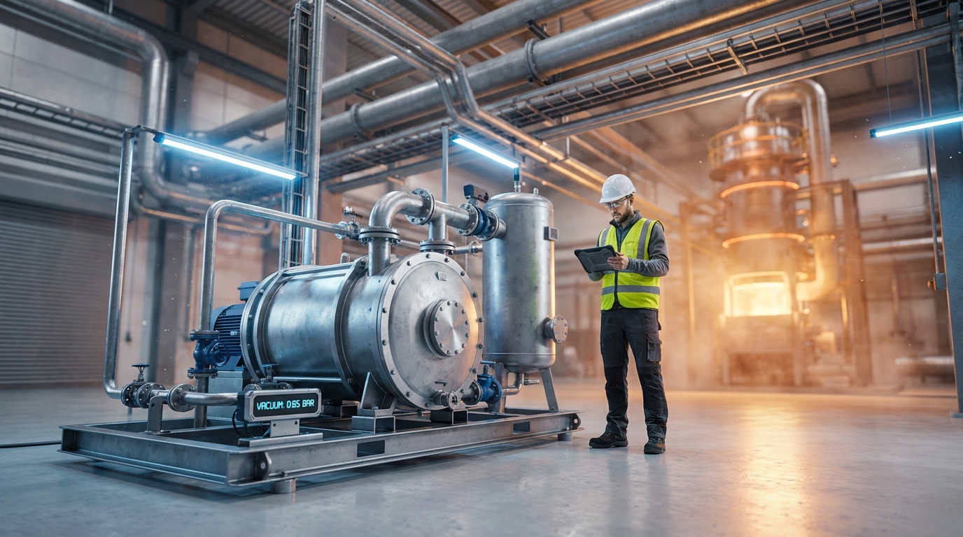
Vacuum is not simply emptiness—it is a precisely controlled physical state that drives some of the most critical industrial processes on a production floor. From degassing molten aluminum in a foundry to lowering boiling points in chemical distillation columns, from vacuum die casting to pneumatic conveying, the ability to create and sustain sub-atmospheric pressure is indispensable. At the heart of every such system sits a vacuum pump, a device whose working principle is deceptively simple yet whose correct application demands genuine engineering understanding.
For factory owners, maintenance engineers, and process designers, knowing the working principle of a vacuum pump is not about academic curiosity. It is about specifying the right equipment, diagnosing performance degradation before it causes downtime, and managing energy and water costs that directly affect the bottom line. This article unpacks the core mechanisms, explores the dominant industrial pump types, and offers practical guidance drawn from real production environments.
What Is a Vacuum, and Why Does It Matter?
A vacuum is any space where the gaseous pressure is below atmospheric pressure. In industrial terms, what matters is not the absolute emptiness but the pressure differential—the gap between the process vessel and the surrounding atmosphere. Gas molecules naturally flow from regions of high pressure to low pressure to equalize the system. A vacuum pump does not “suck” in the traditional sense; rather, it removes gas molecules from a sealed volume, creating a low-pressure zone into which process gases then flow naturally.
Industrial vacuum levels are categorized into distinct bands: rough vacuum (atmospheric to 1 mbar), fine vacuum, high vacuum, and ultra-high vacuum. Most heavy industrial processes—casting, distillation, drying, and pneumatic transport—operate in the rough vacuum range, typically between 100 mbar and 500 mbar absolute. This is the domain where positive displacement pumps, particularly the liquid ring type, have dominated for over a century.
Methods of Creating Vacuum: Two Fundamental Approaches
Broadly speaking, the working principle of a vacuum pump falls into one of two categories:
Gas transfer pumps physically remove gas molecules from a process volume and discharge them into the atmosphere. They use mechanical compression to reduce internal pressure. This category includes liquid ring, rotary vane, dry screw, claw, and diaphragm pumps—all positive displacement machines at their core.
Entrapment (capture) pumps use cryogenic surfaces, magnetic fields, or chemical reactions to trap gas molecules within a confined space. These have no moving parts and are used exclusively for ultra-high vacuum applications.
For the overwhelming majority of foundries, chemical plants, food processing lines, and manufacturing facilities, gas transfer pumps are the workhorse technology. And within that family, no design is more widely deployed than the water ring vacuum pump.
Inside the Water Ring Vacuum Pump: A Step-by-Step Explanation
To grasp the working principle of a vacuum pump in its most practical industrial form, consider the liquid ring pump, commonly called the water ring vacuum pump. Its mechanism was first patented in the 1890s and remains highly relevant today due to its robustness and tolerance for wet, dirty gas streams.
The Key Components
A water ring vacuum pump consists of a cylindrical casing, an impeller mounted eccentrically (off-center) within that casing, inlet and discharge ports, and a quantity of operating liquid—typically water. The eccentric impeller position is the critical design element that makes the entire pumping cycle possible.
The Pumping Cycle
Step 1: Priming and Startup. Before the pump is started, the casing is filled approximately halfway with water. The impeller blades are partially submerged.
Step 2: Formation of the Water Ring. When the motor drives the impeller into rotation, centrifugal force flings the water outward against the cylindrical casing wall. This creates a rotating, ring-shaped body of water that hugs the casing circumference. Because the impeller is not centered, the depth to which the blades are immersed in this water ring varies continuously as the impeller rotates.
Step 3: The Crescent-Shaped Working Space. The eccentric impeller and the water ring together form a crescent-moon-shaped void between the impeller hub and the water ring’s inner surface. This void is divided into individual chambers by the impeller blades. As the impeller rotates, these chambers undergo a continuous cycle of expansion and contraction.
Step 4: Suction (Gas Intake). During the first half of rotation, as individual blades emerge from the water ring, the volume of the space between each blade pair expands. Just as pulling back the plunger of a syringe creates a low-pressure cavity, this expanding volume creates a partial vacuum. Process gas is drawn in through the inlet port to fill this low-pressure zone.
To understand this intuitively, imagine a bucket filled with water and a drinking glass. Submerge the glass in the bucket, invert it, and slowly lift it upward. You feel resistance—the glass resists coming free of the water surface because a vacuum is created inside the glass as it rises. The water clings to the glass, pulled upward by the low-pressure zone inside. The same physical principle operates in the water ring pump: as the impeller blade pulls away from the water ring, it creates an expanding void that draws in gas.
Step 5: Compression and Discharge. During the second half of rotation, the returning blades plunge progressively deeper into the water ring, causing the chamber volume to shrink. The trapped gas is compressed as the chamber contracts. When the pressure inside the chamber exceeds the external discharge pressure, the compressed gas—along with a small amount of the operating liquid—is expelled through the discharge port into a separator vessel.
Step 6: Separation and Recirculation. The discharged mixture of gas and water enters a separator vessel (often called a catch pot or separator tank). Here, the non-condensable gases rise and vent to atmosphere, while the liquid settles to the bottom. A circulation pump returns this water to the vacuum pump, often passing through a heat exchanger first to control temperature. Makeup water is added as needed to compensate for evaporation and carryover.
Why Water Matters Beyond Sealing
The operating liquid in a water ring vacuum pump performs multiple simultaneous functions: it forms the sealing ring that divides the crescent space into discrete pumping chambers; it absorbs the heat of compression, keeping the pump essentially isothermal; it captures any condensable vapors or liquid slugs carried in the process gas stream; and it provides lubrication between the impeller and casing, eliminating metal-to-metal contact.
This multifunctional role explains why the water ring pump handles wet, saturated, and even mildly contaminated gas streams that would destroy other pump types. It also explains the technology’s enduring relevance in foundry vacuum systems, distillation columns, and food processing lines, where process gases are rarely clean or dry.
Other Industrial Vacuum Pump Types: An Overview
While the water ring pump is the most common industrial workhorse, the working principle of a vacuum pump varies significantly across other designs. Understanding the differences informs better equipment selection.
| Pump Type | Operating Principle | Key Advantage | Key Limitation |
| Liquid Ring (Water Ring) | Eccentric impeller compresses gas against a liquid seal | Tolerates wet/dirty gas; very robust | High water consumption; limited vacuum level (~33 mbar) |
| Rotary Vane | Oil-lubricated sliding vanes in an eccentric rotor | Good vacuum level (~0.5 mbar); compact; quiet | Requires regular oil and filter changes |
| Dry Screw | Two counter-rotating screw rotors compress gas without fluid | No oil or water in process space; 30% more energy-efficient than water ring | Higher capital cost; operates at elevated temperatures |
| Dry Claw | Two claw-shaped rotors rotate without contact | Zero maintenance on claw elements; oil-free | Loud operation; limited vacuum |
| Diaphragm | Flexible diaphragm reciprocates to pump gas | Completely oil-free; low maintenance | Low flow capacity; not suited for large industrial systems |
The liquid ring is the “wet” pump; the screw and claw are “dry” pumps that operate without any working fluid in the compression space.
Real-World Applications: From Foundry to Pharma
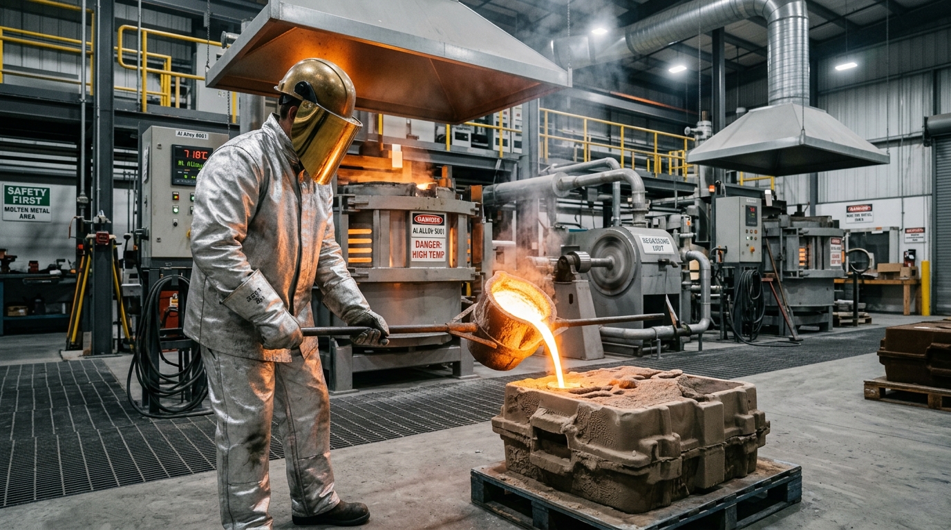
The working principle of the vacuum pump finds practical expression across a remarkable range of industrial sectors. In vacuum die casting and vacuum melting operations for aluminum and steel, vacuum pumps evacuate air from molds to prevent porosity and oxide formation, directly improving casting integrity. In chemical and petroleum distillation, vacuum reduces the boiling point of process fluids, allowing separation at lower temperatures and preventing thermal degradation of heat-sensitive compounds. Food processing applications including milk evaporation, fruit concentration, and poultry evisceration rely on vacuum pumps.
In the plastics industry, vacuum is used for expanded polystyrene forming, thermoforming, and extrusion degassing. Pulp and paper mills depend on vacuum pumps for dewatering on the paper machine wire section. And across all industries, vacuum systems drive pneumatic conveying lines that transport powders, granules, and bulk solids through closed pipelines.
What unites these diverse applications is a shared reliance on stable, predictable vacuum—and a shared vulnerability to pump failure.
Practical Troubleshooting: Diagnosing Vacuum System Issues
For plant engineers and maintenance teams, one of the most common diagnostic scenarios involves confirming where a vacuum drop is occurring. Systematic troubleshooting follows a logical progression:
First: Verify the pump itself. Check vacuum level at the catch pot using a calibrated pressure gauge or manometer. If the pump achieves its rated vacuum here, it is functioning correctly. The problem lies further downstream.
Second: Isolate the line. If vacuum at the catch pot is normal but the process equipment does not reach adequate vacuum, investigate the interconnecting piping: look for leaks, partially closed valves, or condensate accumulation that is restricting flow.
Third: Monitor the operating liquid. For water ring pumps, the temperature of the circulating water is critical. If the water becomes too hot, cavitation occurs within the pump, vacuum performance drops sharply, and the impeller can suffer rapid damage. Heat exchangers and cooling towers that maintain water temperature are not auxiliary systems—they are integral to pump reliability and must be inspected regularly.
Fourth: Empty the catch pot. A catch pot that has filled with condensate or process carryover will not allow proper gas passage. This is a routine operational check that is frequently overlooked.
The Water and Energy Equation: Efficiency Considerations
The most frequently cited limitation of water ring vacuum pumps is their consumption of water and electricity. A once-through 5 HP water ring pump can use over 600 gallons of water per day, roughly 0.5 gallons per minute per rated horsepower. Operating costs from water and wastewater treatment alone can exceed several hundred dollars per year for a single small pump. Additionally, liquid ring pumps run at relatively high speeds to maintain the water seal, which consumes more energy than dry pump alternatives.
Dry vacuum pumps eliminate this water consumption entirely and are approximately 30% more energy-efficient. They also offer longer service lives—typically 15 to 20 years, versus 6 to 8 years for a liquid ring unit. The trade-off is higher initial capital cost (approximately twice that of an equivalent liquid ring pump), louder operating noise, and elevated exhaust temperatures that require safety consideration.
The decision between wet and dry technology is therefore not a simple “which is better” question. It depends on the gas composition (wet processes naturally favor liquid ring), available utilities infrastructure, energy costs, and water scarcity in the region.
The Future: Smart, Connected Vacuum Systems
The working principle of the vacuum pump is being transformed by digital connectivity. Industry 4.0 integration is bringing IoT-enabled pumps with embedded sensors, digital twins, remote monitoring, and predictive maintenance algorithms to the plant floor. Variable-speed drives adjust pump speed to match real-time demand rather than running continuously at full capacity, saving substantial energy. Emerging technologies such as lightweight thin-film vacuum pumps and electrically driven vacuum generators are pushing efficiency further, with some systems achieving up to 95% energy savings compared to compressed-air-driven ejectors.
The global vacuum pump market—valued between
3.13billionand
3.13billionand6.61 billion in 2024 depending on scope, and projected to reach up to $11.41 billion by 2034—is being driven by expanding semiconductor fabrication, chemical processing, and industrial automation, with the Asia-Pacific region contributing over 45% of global demand.
Watch: Vacuum Pump Casting Process Explained
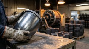
The principles of vacuum are not only applied in pump operation but are also critical during the manufacturing of the pump components themselves. For a practical, on-the-ground look at how vacuum pump castings are produced—from mold preparation to metal pouring—watch this detailed process video from the Make Like PRO channel:
Watch: [https://youtu.be/mIhGfjM1J1Q] Explained
This footage demonstrates real foundry workflows used to cast pump housings, impellers, and casings, directly connecting the theory of vacuum pumps to the manufacturing reality that factory owners and metal casting professionals manage every day. For further hands-on insights into metalworking, casting, and industrial fabrication, the Make Like PRO YouTube channel at https://www.youtube.com/@makelikepro00 is a valuable resource for shop-floor knowledge.
Conclusion
The working principle of a vacuum pump is conceptually straightforward: remove gas molecules from a sealed volume to create a pressure differential. But the engineering reality—in the choice between liquid ring and dry screw, in the management of water chemistry and heat exchangers, in the systematic diagnosis of vacuum loss—is where plant reliability, product quality, and energy cost are determined. For factory owners and process engineers, understanding these principles not as abstract physics but as daily operational realities is what separates efficient, predictable production from recurring downtime and quality deviations.
A vacuum pump is rarely the most visible asset on a factory floor. But when it fails, it is always the most noticed one. Investing in the right technology, maintaining it with discipline, and monitoring it with modern digital tools ensures that the invisible force of vacuum continues to serve the visible goals of quality, throughput, and profitability.


Post Comment